Lenovo Storage Array 8332 Bedienungsanleitung Seite 15
- Seite / 44
- Inhaltsverzeichnis
- LESEZEICHEN
- Secure Managed Client 1
- Storage Array User Guide 1
- User Gui de 3
- Contents 5
- User Guide 6
- Introduction 7
- 2 User Guide 10
- Chapter 2. Features 11
- Enclosure subsystem 12
- Enclosure chassis 13
- Server board subdivision 14
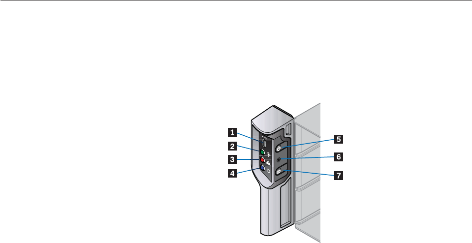
- Server board I/O panel 14
- Server board LEDs 15
- Connectors 15
- Rear panel 16
- Power supply unit 16
- Cooling fans 17
- Drive carrier module 18
- Drive status indicator 19
- Anti-tamper locks 19
- 12 User Guide 20
- Planning your installation 21
- 14 User Guide 22
- Rail kit assembly 24
- Enclosure installation 24
- Power cord connection 25
- Grounding checks 25
- 18 User Guide 26
- Chapter 4. Operation 27
- 20 User Guide 28
- Starting the drives 29
- Disk drive LEDs 29
- BIOS settings 30
- Turning off 30
- 24 User Guide 32
- Cooling fan LEDs 33
- Drive carrier module LEDs 33
- Rear panel LED 33
- Audible alarms 34
- Alarm interpretation 34
- Troubleshooting 36
- System faults 36
- Power supply unit faults 36
- Cooling fan faults 37
- Thermal cooling 37
- 30 User Guide 38
- 32 User Guide 40
- Chapter 6. Notices 41
- Trademarks 42
- Part Number: 45K1342 44
- Printed in USA 44
- (1P) P/N: 45K1342 44
Verwandte Produkte und Handbücher für Computergehäuse Lenovo Storage Array 8332
 (4 Seiten)
© 2020, manymanuals.de. Alle Rechte vorbehalten. | 0.326 s |
 Manymanuals.com
 Manymanuals.de
 Manymanuals.fr
 Manymanuals.it
 Manymanuals.pl
 Manymanuals.cz
 Manymanuals.es
 Manymanuals-pt.com
Kommentare zu diesen Handbüchern